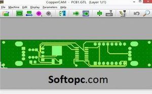
CopperCAM v25032016 provides you with simple-to-use tools for engraving, drilling, and cutting PCB prototypes. The PCB Engraver is a convenient tool for creating PCBs from an image. To use this tool, you must create a new PCB in the PCB Editor and then run a script file with it.
CopperCAM v25032016 is designed to work directly with your CNC machine or mill without the need of integrating it into your CAM software. This is perfect for smaller shops or individual designers who are looking to save time. This plug-in will simplify the job of machining prototypes by allowing users to machine multiple parts at once. It can also be used to make models for other processes such as 3D printing. CopperCAM contains only the most needed features which allow you to work directly on your projects without any restrictions.
Overview of CopperCAM v25032016
It is a software application developed to provide structural engineers with the tools required to model, design, and analyze structures using 3D CAD systems. The script file must have the .cupe extension. The PCB Engraver does not support any command-line parameters. PCB Engraver The PCB Engraver converts a PCB image into a usable PCB in the designated PCB Editor workspace.
The PCB Image must be a PNG file and can optionally include a color layer. The PCB Engraver is invoked from the PCB Editor’s Edit » PCB » Convert to the PCB menu or from the Tools menu. In either case, a single PCB workspace is designated as the target workspace.
It features advanced technological functions for the automatic processing of solid models, providing orthographic and perspective views, as well as spreadsheet-style formatted design sheets. CopperCAM provides advanced technology for processing solid models, producing orthographic and perspective views, as well as spreadsheet-style formatted design sheets. They specialize in helping companies develop their copper mining capabilities and ensure that they are compliant with the new environmental protection law.
The present-day world’s demand for copper is so high, they can’t fulfill all of it. CopperCAM helps do this by developing the copper mines and supplying the most reputable chip makers. As surveillance technology continues to progress, video surveillance is quickly becoming a staple of the average workplace. CopperCAM v25032016 is a new app that can be used to live stream video from your iPhone or iPad to a variety of devices.
It is a professional software application for engineers and general contractors. The application can be used to take measurements and design, visualize, and review your construction projects. The software features standard construction tools such as tape measures, levels, and laser levels. It also includes import and export options for transferring your data. It also features a nice, intuitive interface that is easy to use. Essential Apps for Surveyors We surveyed the iTunes App Store for apps related to surveyors and found quite a few options.

Top Features of CopperCAM v25032016
Some of the top features of CopperCAM v25032016 are;
- It comes with a built-in simulator that allows the user to simulate any event on a design.
- It has a library of more than 10,000 components and tools.
- It includes hole makers, board-cutters, logic analyzers, and trackers.
- It has more than 35 program languages for the database.
- It supports more than 2000 boards and 5000 components.
- It is suitable for design, cutout, milling, drilling, grinding, tapping, hot cutting, engraving, sawing, wire routing, routing of any tracks or patterns on PCB, and printing on paper or screens.
Some Other Interesting Features and Changes
Calculates the cutting lines
CopperCAM v25032016 is a 3D modeling program for designing machined parts with subtractive methods. It can be used to calculate the cutting lines for a metal part on the machine table. The parts can be machined from sheet metal or turning billets. Other features of the program include:
- Material thickness and hardness calculations.
- Creation of custom machining sequences.
- 3D View.
- It has a built-in CAM module for 3+2 and 5+2 machining processes.
It is a powerful tool for accurate cutting lines. It calculates the cutting lines by “cutting up” the object to be cut. As it is designed with lightweight speed and accuracy, it can be run on Windows XP with minimal system requirements. This allows you to save time and money by cutting sheet materials faster and more accurately than ever before.
Manage 4 circuit layers
CopperCAM v25032016 is a 3D circuit visualization software developed by Biosystem for use in designing and simulating electronic circuit boards. It is designed to be easy to use and is ideal for beginners, as well as those with some experience. It can handle 4 circuit layers, as well as up to 20 different devices per layer. These can be a mix of vias, pads, and devices.
The first step is to create a new project. We select our device package. Click OK on the warning message. Now we have a CopperCAM v25032016 schematic which is going to be the core of our design. It also includes a library of almost 3000 pre-loaded components to choose from, as well as a wide range of available.
The project is a CAD program for designing printed circuit boards. The new version includes the ability to manage 4 circuit layers, as well as many other new features. File formats supported: – *.PCB (native) – *.BRD (brd) – *.CDR (cam, cdr, rsrc) – *.ASM (asm) – *.OBJ (obj) – *.STL (stl)

Isolation engraving
Isolation engraving is a technique where the cutting lines and the ground surface are generated separately. This technique eliminates the need for a ground line and allows for an accurate representation of the desired cut. In addition, it creates a surface that can be quickly and easily modified in the event of any errors made during the production process. In order to create an isolation engraving for this project, I used my original drawing from class as a guideline.
Isolation engraving has been an important process in the production of printed circuit boards and other types of electronic equipment. As a result of ongoing technological advances, however, other methods have been developed which have made etching unnecessary for certain applications. In the traditional method, a photoresist material is coated onto a metal-coated board, and a pattern is cut into it. CopperCAM v25032016 provides a solution for designers and engineers to create and review layouts and work with native CAD data before finishing the design and manufacturing process.
Import of Gerber & Excellon files
It is a professional-level CAD/CAM software suite that provides an intuitive interface for designing and generating 3D models, routing 2D outlines of profiles, or creating NC files for cutting tools. The import of Gerber & Excellon files will allow the user to import existing designs from a PCB manufacturer, and update them with PCB information such as layers, pads, and copper.
The Gerber & Excellon import allows the user to select a list of all files or a specific file from a design. Each file can be updated with copper and layer information, including all required drill file import options.
It is a software package for the design and manufacturing of printed circuit boards. In this latest release, CopperCAM now supports importing Gerber & Excellon files, as well as exporting print & drill files in Gerber format. The program also supports the use of color to distinguish layers. Following is a list of the major changes: 1. Added Gerber and Excellon file import/export 2. Added layer color coding 3. Added layer name and number on printed output (Gerber only) 4.
Drilling and cutting PCB prototypes:
CopperCAM v25032016 is an efficient tool for drilling and cutting PCB prototypes. It is capable of making five different types of holes in copper-clad boards, including single-drill holes, double-drill holes, single-cut holes, double-cut holes, and quadrant-cut holes. Other features include hole alignment, automatic loading of all drills with no need to change drill bits, and the use of the same legend to provide options for different tools.
In this manner, both the second and third embodiments have been disclosed as providing a wide range of versatility in use. In particular, the diagrams referred to herein illustrate a process for creating a tool legend. This provides a flexible arrangement that can be applied to a variety of similar tools.
A company that specializes in the development of PCB prototypes and thin-film coatings, has released it. The new version includes the ability to operate on native Windows, as well as various bug fixes and performance improvements. The program is designed to connect several sheets of PCB through an internal bus, which can be used to exchange data between devices.
